Wiring Diagram For Ford Alternator With Internal Regulator Wiring
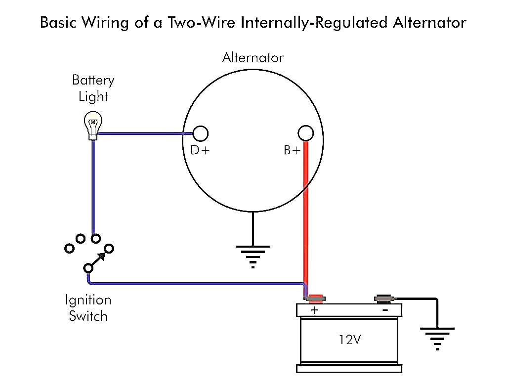
2 wire alternator wiring diagram. A 2-wire alternator has three connections, the first being the ground. This connection is also called the output connection. It allows power to flow through the alternator and other components of your car. The second connection is the positive (possibly fuseable) terminal and is connected directly to the battery.
Delco Alternator Wiring Diagram External Regulator Wiring Diagram
A 4-wire alternator wiring diagram provides a comprehensive guide on how to connect the alternator to the rest of the electrical system. Within a 4-wire alternator wiring diagram, you will find the four essential connections required for proper operation: the main battery positive wire, the ignition wire, the voltage sensing wire, and the field.
2 Wire Alternator Wiring Diagram Wiring Diagram
4 Wire Alternator Wiring Diagram is the linchpin of a vehicle's electrical system, seamlessly connecting components from the GM to Delco. It ensures an efficient conversion of alternating current from the alternator to direct current for your battery, harmonizing the electrical demands of any car, whether Ford or Chevrolet.
0911 ctsv alternator wiring LS1TECH Camaro and Firebird Forum
An alternator is an essential component in a vehicle's electrical system. It is responsible for generating electricity to power various electrical components and recharge the battery. Understanding the basic wiring diagram of an alternator is crucial for troubleshooting electrical issues and performing proper installations or repairs.

Delco Alternator Wiring Diagram Free Wiring Diagram
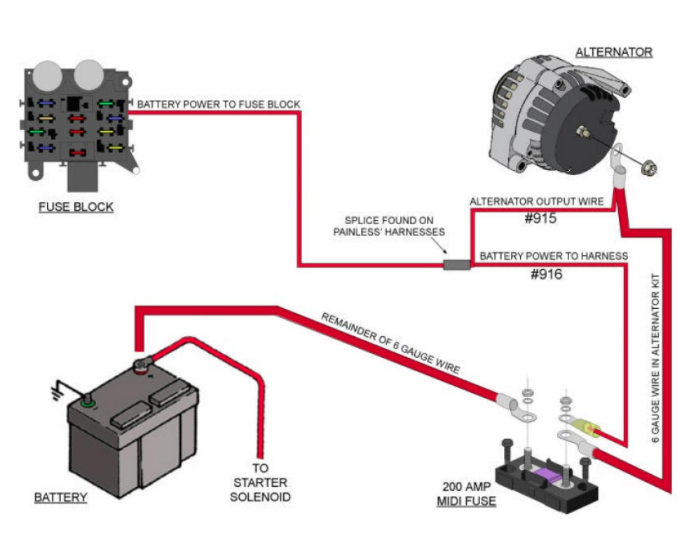
Alternator Wiring Kit 555 -10510 100 Amps 8 gauge 150 Amps 6 gauge 200 Amps 4 gauge It is very important to use the correct wire size to connect the alternator to the battery. A wire size too small can allow the wire to overheat, melt the insulation and cause a fire or worse..

Denso Alternator Wiring Schematic Free Wiring Diagram
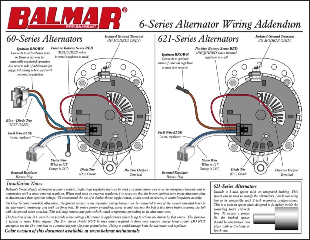
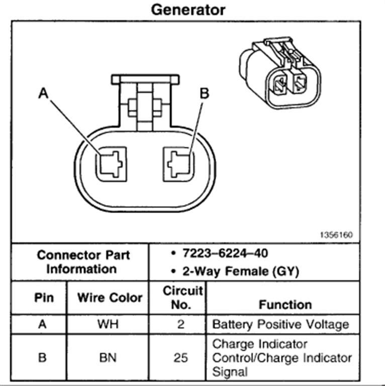
You will have to understand the wiring diagram for this (see the table below). Also, see under 'Identifying the Wiring' and Step 4 to know what wire goes where. When connecting the voltage regulator to the alternator, it is usually the blue wire to the terminal that might also be marked 'F'.
Si Alternator Wiring Diagram Wiring Diagram Alternator To Battery
A 4 wire alternator wiring diagram typically consists of two parts. The first part is the schematic, which shows all the components and their connections. The second part is the wiring diagram, which indicates the route of the wiring and the exact location of each component. Although a 4 wire alternator wiring diagram may seem confusing, it can.
1986 chevy 350 alternator wiring
A typical 3-wire alternator wiring diagram with an internal voltage regulator. Computer-Controlled Voltage Regulation. Many late-model vehicles use the engine computer, which is often referred to as the powertrain control module (PCM), to control alternator output. Most modules use an internal driver to turn the alternator's field circuit on.

Delco Alternator Wiring Diagram Free Wiring Diagram
The three-wire alternator wiring diagram is a multi-purpose alternator that has built-in voltage rectifiers for power sensing, ensuring regulated voltage for all components. The external electromechanical voltage regulator involves coiling the voltage sensing cable into an electromagnet and attracts the ferrous block towards itself.

Callie Wiring Motorola Marine Alternator Wiring Diagram 300
9 - If installing an alternator with OEM wiring connections, reconnect alternator wires and battery ground cable. If installing a 1-wire alternator, see wiring instructions at upper right. 10 - Make sure battery is fully charged before starting engine. 11 - Reconnect the ground cable, start the engine and using a VOM meter, verify that the.
Valeo Alternator Wiring Diagram Collection
Alternator Wiring Diagrams. Below given are some alternator wiring diagrams that are used for different purposes. Let's have a look at their connections. 3 Wire Alternator Wiring Diagram. This is a three-wire alternating wiring diagram showing the connections between the different components of a circuit.

Wiring Diagram Volvo Penta Alternator
Wiring a 12 volt Bosch alternator may seem like a complex task, but with the right guide, it can be a straightforward process. Whether you're upgrading your vehicle's electrical system or replacing a faulty alternator, understanding the wiring process is crucial to ensuring the proper functioning of your vehicle.

12 Volt Alternator Wiring Schematic Free Wiring Diagram
Step #10 Start engine and test alternator. While engine is at idle, take a screwdriver or pocket knife and place on the back of the alternator bearing surface, (the round area in the middle of the back of alternator). Your alternator is working when you can feel a magnetic pull on the knife or screwdriver. You can also check the amp / volt meter by

7127 Alternator Wiring Diagram
Wiring an alternator warning light is fairly straightforward, and the procedure is the same regardless of the car or truck you're working on. In this article, we'll discuss the basics of wiring an alternator… Read More ». Types of Wiring Diagrams When it comes to wiring diagrams, there are two main types: schematic diagrams and.
2002 alternator wiring schematic Forums
Understanding the Wiring Diagram. To understand the wiring diagram for a one wire alternator, it is important to first have an understanding of the components of the system. The alternator itself is a generator that sends electricity to the battery. It is powered by the car's engine and is responsible for providing power to the electrical system.

Gm Alternator Wiring Schematic Free Wiring Diagram
The wiring diagram of a Bosch alternator illustrates the various connections and components involved in the charging system. It depicts the internal circuitry and connections of the alternator, including the voltage regulator, diode trio, and rotor. The diagram also shows the connections to the battery, ignition switch, and various electrical.